Understanding MIDI Messages: From Bits and Bytes to Music
What is MIDI, anyway?
The year is 1983. At the winter NAMM Show, two synthesizers appear that are about to make music history: the Sequential Circuits Prophet-600 and Roland’s Jupiter-6. For the very first time, two synthesizers from different manufacturers can talk to each other — through a shared, standardised protocol called MIDI (Musical Instrument Digital Interface).
MIDI was originally developed with the simple goal of connecting two keyboards so both could be played simultaneously from a single set of keys. Today, the scope is far broader: virtually every musically relevant parameter can be controlled via MIDI. You can address multiple parts or sounds across one or more instruments, switch between sounds on the fly, or even reprogram instruments remotely. Effects units are MIDI-controllable too, enabling everything from subtle to dramatic sonic transformations.
Devices like sequencers (Roland MSQ-700 was the first MIDI sequencer, Sequential Model 64 the first software MIDI sequencer), drum computers, and DAWs can be synchronously started, stopped, and scrubbed — much like a tape machine. Various sub-standards also handle digital audio transfer, tape machine synchronisation, and cue list delivery for film and video post-production.
And MIDI instruments are by no means limited to keyboards as controllers. Thanks to MIDI-capable guitars, violins, wind instruments, drums, and accordions, non-keyboardists can access the sonic world of MIDI instruments just as easily.
MIDI doesn’t transmit sound. MIDI transmits commands — the way a score tells an orchestra what to play, without being music itself. Via MIDI, one device can control others.
When you draw a note in Logic Pro’s Piano Roll, nothing acoustic happens yet. Logic stores a message — a short sequence of bytes saying: Note On, Channel 1, Pitch 60, Velocity 100. The synthesiser plugin receives that message and decides for itself what sound to make from it. MIDI and audio are completely separate layers.
This post goes deep into the byte level of MIDI. If you’ve ever wondered why MIDI has 128 velocity steps, why channel numbers run internally as 0–15 but display as 1–16, or how SysEx can carry arbitrary manufacturer data — here’s your explanation.
Binary and Hexadecimal
To really understand MIDI, you need a quick detour through the world of number systems. Don’t worry — it’s easier than it sounds.
The Binary System
Computers store everything as voltage states: on or off. Those states are represented as 1 and 0. That’s binary. A single on/off state is a bit. Eight bits make a byte. One byte can represent 256 different values (0–255), because 2⁸ = 256.
A byte has 8 positions (bits). The leftmost position is the Most Significant Bit (MSB), the rightmost is the Least Significant Bit (LSB). The value of each position doubles as you move from right to left.
Bit positions within a byte are numbered right to left, starting at 0. Each position represents a power of 2:
| Bit Position | 7 | 6 | 5 | 4 | 3 | 2 | 1 | 0 |
|---|---|---|---|---|---|---|---|---|
| Value | 128 | 64 | 32 | 16 | 8 | 4 | 2 | 1 |
| Decimal | Binary | Meaning |
|---|---|---|
| 0 | 0000 0000 | Zero |
| 1 | 0000 0001 | One |
| 2 | 0000 0010 | Two (bit 1 set) |
| 4 | 0000 0100 | Four (bit 2 set) |
| 8 | 0000 1000 | Eight (bit 3 set) |
| 15 | 0000 1111 | All 4 bits set = maximum |
| 128 | 1000 0000 | |
| 255 | 1111 1111 |
In MIDI messages, the MSB is used to distinguish whether a byte is a status byte or a data byte. That means a range of 0–127 — 128 values — is available for data.
Hexadecimal
Binary numbers are precise, but painful to read. That’s why engineers use the hexadecimal system (hex for short). It has 16 characters: 0–9 and A–F. One hex digit represents exactly 4 bits — and a pair of hex digits describes a complete byte precisely.
QUICK RULE One byte = 8 bits = 2 hex digits.
9FHmeans:9=1001binary,F=1111binary → together1001 1111binary = 159 decimal.
The Nibble Principle — no maths required
A byte naturally splits into two nibbles of 4 bits each. The upper nibble is bits 7–4, the lower nibble is bits 3–0. Each nibble maps to exactly one hex digit. You can read hex from binary by splitting the byte in half and looking up each half in a table — no calculation needed.
Binary:   1001 0110
          ────  ────
Upper:    1001  = 9
Lower:    0110  = 6
Hex:      0x96
It works in reverse too: 0x96 → upper digit 9 = 1001, lower digit 6 = 0110 → 10010110.
| Binary | Hex | Binary | Hex | |
|---|---|---|---|---|
| 0000 | 0 | 1000 | 8 | |
| 0001 | 1 | 1001 | 9 | |
| 0010 | 2 | 1010 | A | |
| 0011 | 3 | 1011 | B | |
| 0100 | 4 | 1100 | C | |
| 0101 | 5 | 1101 | D | |
| 0110 | 6 | 1110 | E | |
| 0111 | 7 | 1111 | F |
The 0x Prefix — why does it appear before every hex number?
In MIDI documentation, synthesiser manuals, and code you constantly encounter notation like 0x96, 0x3C, or 0xF0. The 0x in front is not a value — it’s a pure marker: “this number is hexadecimal, not decimal.”
The problem without a prefix: what does 96 mean on its own? Ninety-six decimal — or hex (= 150 decimal)? Ambiguous. With a prefix, it’s unambiguous.
| Notation | System | Decimal value | MIDI meaning |
|---|---|---|---|
150 | Decimal | 150 | not easy to read at a glance |
0x96 | Hexadecimal (C-style) | 150 | Note On, Channel 7 (immediately visible) |
96H | Hexadecimal (MIDI notation) | 150 | common in Roland/Yamaha manuals |
10010110 | Binary | 150 | precise, but unwieldy |
The 0x prefix originated in the C programming language (1970s) and has been adopted by nearly every language since. MIDI manuals from manufacturers often use a trailing H: 96H instead of 0x96. Both mean the same thing. This post uses both notations.
Interactive Widget: Binary ↔ Hex Converter
Click the bits to toggle them and watch the hex and decimal values update in real time. The upper nibble (bits 7–4) is shown in Cyan, the lower nibble (bits 3–0) in Violet. Use the presets to load common MIDI bytes.
Status Bytes and Data Bytes
The Bit-7 Rule
Every MIDI message starts with a status byte. The defining characteristic: bit 7 is set to 1. Every subsequent data byte in that message has bit 7 set to 0. This single rule lets a receiver always tell whether an incoming byte is a new command or a continuation byte — with no start/stop framing needed.
The byte value 128 (1000 0000 binary) is the smallest possible status byte. Values 0–127 are data bytes. Values 128–255 are status bytes.
Why is it called “Bit 7” — not Bit 1 or Bit 8?
This is a common source of confusion. Bits are counted from the right, starting at 0 — exactly like digits in the decimal system. The reason is mathematical: each position corresponds to a power of two, and the smallest power of two is 2⁰ = 1, not 2¹.
Position:   7    6    5    4    3    2    1    0
            │    │    │    │    │    │    │    │
Value:     128   64   32   16    8    4    2    1

Example: 0x96 = 150 decimal
Bits:      1    0    0    1    0    1    1    0
          128 + 0 + 0 + 16 + 0 + 4 + 2 + 0 = 150 ✓
Bit 7 (far left) is the Most Significant Bit (MSB) — with a value of 128, it has the greatest influence on the overall number. Bit 0 (far right) is the Least Significant Bit (LSB) with a value of 1. In the MIDI protocol, bit 7 is the only difference between a status byte and a data byte — a single bit decides the role of the entire byte.
MSB/LSB — two levels, one recognition rule: MIDI documentation uses MSB and LSB on two levels. Bit level: “Bit 7 is the MSB” — referring to a position within a single byte. Byte level: “CC 7 is the MSB controller” — referring to a whole MIDI byte when a value is distributed across two bytes (e.g. 14-bit Pitch Bend). You can tell the level from the accompanying word: if Bit precedes it → bit level. If Byte, Controller, or Data precede it → byte level.
Anatomy of the Status Byte
The status byte encodes two pieces of information in its two nibbles:
The upper nibble (bits 7–4) encodes the message type. The lower nibble (bits 3–0) encodes the MIDI channel (0–15, displayed as 1–16 in software). Bit numbering counts from the right, starting at 0 — so bit 0 is the least significant (rightmost) bit.
Example: 0x92
0x92 = 1001 0010
       ────  ────
Upper: 1001  = 9  → Message type: Note On (0x9n)
Lower: 0010  = 2  → Channel: 2 (displayed as Channel 3 in Logic)
Logic Tip: Window → MIDI Monitor (or the MIDI Monitor object in the Environment) to watch raw MIDI messages arrive in real time. Every status byte, every CC value — live as it hits. Indispensable for debugging controllers and hardware.
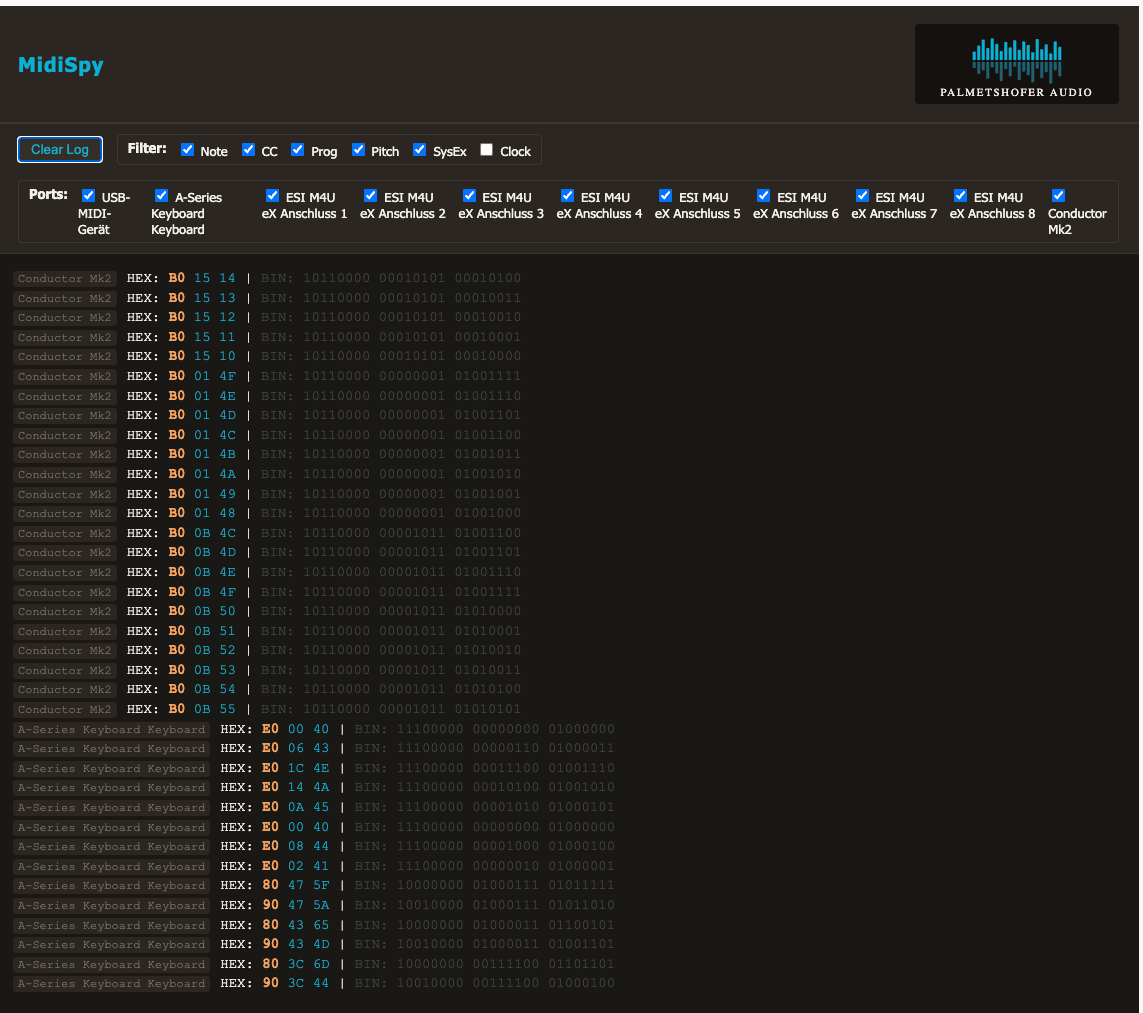
If you need a DAW-independent view of your MIDI data: MidiSpy by Palmetshofer Audio is a browser-based MIDI monitor delivered as a single HTML file — no installation, no server, no internet connection required. Just open it, connect your MIDI device, and watch the messages roll in.
Message Types at a Glance
Before we dig into individual messages, a quick orientation — so you know where Note On sits in the bigger picture.
Every MIDI message always consists of a status byte followed by zero to two data bytes. You saw that in the previous section. What changes is the content of those bytes — what the command means and who it’s addressing.
MIDI distinguishes two fundamental addressing modes:
Channel messages are directed at a specific MIDI channel. Think of it like a mixing desk with 16 channels: a channel message doesn’t just say “play a note”, it says “play a note on Channel 3”. Only the instrument listening on Channel 3 responds. Note On, Note Off, Control Change, and Pitch Bend are all channel messages.
System messages, on the other hand, have no channel address — they apply to all devices simultaneously. Tempo synchronisation (MIDI Clock) or halting all devices (Stop) doesn’t make sense per-channel, so those get system messages.
This distinction — channel vs. system — describes who a message is addressing. It has nothing to do with how the message is structured. Status byte and data bytes are the structure of every message; channel vs. system is the addressing.
| Type | Hex | Purpose | Bytes |
|---|---|---|---|
| Note Off | 0x8n | Key released | 3 |
| Note On | 0x9n | Key pressed | 3 |
| Control Change | 0xBn | Knobs, pedals | 3 |
| Program Change | 0xCn | Sound selection | 2 |
| Pitch Bend | 0xEn | Pitch shift | 3 |
| MIDI Clock | 0xF8 | Tempo sync | 1 |
| System Exclusive | 0xF0 | Manufacturer data | variable |
The n in the hex values stands for the channel (0–15). You can identify system messages by the upper nibble F (1111 in binary). The lower nibble then no longer encodes the channel — it encodes the exact type:
Channel message:  0x9n
                  │└── Channel (0–15)
                  └─── Message type (Note On)

System message:   0xF8
                  │└── which one? (8 = MIDI Clock)
                  └─── always F → "this is a system message"
No n in the lower nibble anymore — that space belongs to the type, not the channel. Now let’s look at the most important type in detail: Note On.
Note On — a key is pressed
When you press a key on your keyboard, Logic sends a Note On message. That message consists of exactly three bytes — no more, no less.
Byte 1: Status Byte  → What's happening, on which channel?
Byte 2: Data Byte 1  → Which note?
Byte 3: Data Byte 2  → How loud?
Byte 1: The Status Byte
The status byte packs two pieces of information into a single byte. The upper nibble (bits 7–4) encodes the message type, the lower nibble (bits 3–0) the MIDI channel.
For Note On, the upper nibble is always 9. That means:
Channel 1   →  0x90  (1001 0000)
Channel 2   →  0x91  (1001 0001)
Channel 3   →  0x92  (1001 0010)
...
Channel 16  →  0x9F  (1001 1111)
A single byte already tells you: “Note On, Channel 1.” Bit 7 is always 1 — that’s the signature of every status byte.
Byte 2: The Note Number
The second byte determines which note is played. The range is 0–127 (128 values, i.e. 7 bits). Key reference points:
| Note | MIDI Number | Hex |
|---|---|---|
| C (lowest MIDI note) | 0 | 0x00 |
| Middle C (C3 in Logic) | 60 | 0x3C |
| A4 — Concert pitch 440 Hz | 69 | 0x45 |
| G9 (highest MIDI note) | 127 | 0x7F |
Note: Logic displays middle C as C3; other DAWs show it as C4. The underlying byte is 60 in both cases — only the display differs.
Byte 3: Velocity
The third byte determines the strike intensity — how hard the key was pressed. Again: 0–127.
| Velocity | Meaning |
|---|---|
| 0 | Treated as Note Off |
| 1–63 | Piano to mezzo-forte |
| 64 | Approximate midpoint |
| 65–127 | Mezzo-forte to fortissimo |
| 127 | Maximum |
The MIDI spec doesn’t define how velocity translates to volume or timbre — that’s up to the instrument. That’s why velocity 100 sounds different on a Steinway sample than on a synthesiser.
Complete Example
Middle C, Channel 1, Velocity 100:
90 3C 64
│  │  └── Velocity: 100 (decimal) = 0x64
│  └───── Note number: 60 (decimal) = 0x3C = middle C
└──────── Status: Note On, Channel 1 = 0x90
And when the key is released, a Note Off follows — same structure, upper nibble 8 instead of 9:
80 3C 40
│  │  └── Release velocity: 64 (usually ignored)
│  └───── Note number: 60 (middle C)
└──────── Status: Note Off, Channel 1 = 0x80
Practical shortcut: Many devices send a Note On with velocity 0 instead of Note Off.
90 3C 00has exactly the same effect as80 3C 40— and saves switching the status byte.
Velocity and 7-Bit Resolution
Data bytes have a maximum of 7 bits — 128 values (0–127). Velocity 0 = key released, velocity 127 = maximum strike force. Synthesisers of that era couldn’t use more values. MIDI 2.0 changes this.
The relationship between MIDI velocity and perceived loudness is logarithmic in most synthesisers, not linear — because our hearing works logarithmically.
Control Change — Knobs, Pedals, Mod Wheels
Control Change (CC) is the universal transport mechanism for everything that isn’t a note on/off: volume, pan, modulation, sustain, expression. A CC message always consists of three bytes.
Byte 1: Status Byte    → Control Change, on which channel?
Byte 2: Controller No. → Which control?
Byte 3: Value          → How much?
The upper nibble of the status byte is always B (= 1011). The lower nibble is the channel (0–15).
Structure
B0 07 64
│  │  └── Value: 100
│  └───── Controller 7 = Channel Volume
└──────── Status: Control Change, Channel 1 = 0xB0
The Most Important Controller Numbers
| CC# | Function | Typical Use |
|---|---|---|
0 | Bank Select MSB | Switch sound bank (together with CC#32) |
1 | Modulation Wheel | Vibrato, LFO depth |
7 | Channel Volume | Overall channel volume |
10 | Pan | Panorama (0 = left, 64 = centre, 127 = right) |
11 | Expression | Dynamic volume within a part |
64 | Sustain Pedal | 0–63 = off, 64–127 = on |
74 | Brightness / Filter Cutoff | Often mapped to filter opening |
121 | Reset All Controllers | Reset all controls |
123 | All Notes Off | Panic function |
Modulation vs. Expression: CC#1 (Modulation Wheel) typically controls vibrato or LFO depth — a timbral change. CC#11 (Expression) is a dynamic volume within the channel volume (CC#7). Think of CC#7 as the fader and CC#11 as the player’s phrasing.
Sustain pedal pressed (Channel 1):
B0 40 7F
│  │  └── Value 127 = on
│  └───── Controller 64 = Sustain Pedal
└──────── Control Change, Channel 1

Modulation wheel at half position (Channel 2):
B1 01 40
│  │  └── Value 64 = centre
│  └───── Controller 1 = Modulation Wheel
└──────── Control Change, Channel 2
Logic Tip: CC curves can be drawn directly in Logic’s Piano Roll (the lane at the bottom, selector set to “Controller”). You’re looking at the raw byte values there — exactly what travels down the cable.
Program Change — Switching Sounds
Program Change selects a sound (patch) on the target device. It’s the only common MIDI message that gets by with just two bytes — no second data byte needed.
Byte 1: Status Byte  → Program Change, on which channel?
Byte 2: Program No.  → Which sound? (0–127)
The upper nibble is C (= 1100).
C0 18
│  └── Program 24 (decimal) = 0x18
└───── Status: Program Change, Channel 1 = 0xC0
Why Only 128 Sounds?
7-bit data byte = 128 possible values. That was sufficient in 1983. For devices with more patches, there’s Bank Select: CC#0 (MSB) and CC#32 (LSB) first select the bank, then Program Change switches within that bank. Together they address 128 × 128 × 128 = over two million patches — in theory.
Switch bank and load Program 1 in Bank 2 (Channel 1):
B0 00 02   ← Bank Select MSB: Bank 2
B0 20 00   ← Bank Select LSB: 0 (often not needed)
C0 00      ← Program Change: Patch 1 (within the selected bank)
Note: MIDI program numbers run internally from 0–127, but devices and Logic typically display them as 1–128.
C0 00therefore corresponds to Program 1 in the display — not Program 0.
Pitch Bend — Why Does It Get Its Own Message?
Why does Pitch Bend have its own message type with status byte prefix E (1110), instead of being handled as a Control Change?
Resolution. A normal data byte has 7 bits = 128 steps. For Pitch Bend, 128 steps simply aren’t enough: the pitch change sounds stepped and unnatural. So Pitch Bend uses two data bytes for 14-bit resolution — 16,384 steps instead of 128. That gives you a smooth, continuous curve.
Byte 1: Status Byte      → Pitch Bend, on which channel?
Byte 2: Low byte         → Fine value (7 bits)
Byte 3: High byte        → Coarse value (7 bits)
Note on MSB/LSB: In MIDI documentation, the two Pitch Bend data bytes are often labelled “LSB” and “MSB” — but here that does not refer to a bit, it refers to a byte: the Least Significant Byte (low byte) and Most Significant Byte (high byte). This meaning only applies where two bytes are combined into a larger value — in Pitch Bend and in high-resolution CC pairs. Everywhere else in MIDI (status byte, bit-7 rule, etc.), MSB/LSB refers to a single bit.
The neutral value (no pitch change) sits exactly in the middle: decimal 8192.
Pitch Bend: no change (neutral position), Channel 1:
E0 00 40
│  │  └── High byte: 64 (0x40) → upper half = centre
│  └───── Low byte: 0          → no fine tuning
└──────── Status: Pitch Bend, Channel 1 = 0xE0

Pitch Bend: maximum upward bend, Channel 1:
E0 7F 7F
│  │  └── High byte: 127 → maximum
│  └───── Low byte: 127  → maximum
└──────── Status: Pitch Bend, Channel 1 = 0xE0

Pitch Bend: maximum downward bend, Channel 1:
E0 00 00
│  │  └── High byte: 0 → minimum
│  └───── Low byte: 0  → minimum
└──────── Status: Pitch Bend, Channel 1 = 0xE0
Combining Two Bytes into a 14-Bit Value
The two 7-bit bytes are combined into a 14-bit value: the high byte forms the upper 7 bits, the low byte the lower 7 bits.
High byte = 0x40 = 100 0000  (7 bits)
Low byte  = 0x00 = 000 0000  (7 bits)
14-bit value: 100 0000 000 0000 = 8192 → neutral position
Why the low byte first? That’s a quirk of the MIDI spec: Pitch Bend sends the less significant byte before the more significant one. For most other MIDI messages this is irrelevant (because there’s only one data byte), but here the order matters.
Logic Tip: The pitch bend range (how many semitones a full deflection represents) is not part of the MIDI message — it’s set in the receiving instrument. The standard is ±2 semitones, but synthesisers can be configured to ±12 or more. In Logic: Smart Controls or instrument plugin parameters.
System Exclusive
SysEx is the escape hatch in the MIDI protocol — a variable-length message that lets manufacturers send arbitrary data. The format: F0H (start), manufacturer ID, device ID, payload, F7H (end).
SysEx Structure
| Byte | Value | Meaning |
|---|---|---|
| 1 | F0H | SysEx Start |
| 2 | Manufacturer ID | 1 or 3 bytes |
| 3 | Device ID | 0–127 or 7FH (broadcast) |
| 4…n | Data | Any 7-bit values |
| Last | F7H | SysEx End (EOX) |
Manufacturer IDs
| Manufacturer | ID |
|---|---|
| Roland | 41H |
| Yamaha | 43H |
| Korg | 42H |
| Kawai | 40H |
Older manufacturers have 1-byte IDs. Newer ones (post-1987) use 3-byte IDs beginning with 00H.
What manufacturers transmit via SysEx is entirely up to them — the MIDI spec only defines the frame format. In practice, SysEx is used for, among other things:
- Individual sounds (patches): A complete synthesiser sound with all its parameters is transferred as a SysEx dump — allowing presets to be copied between devices or archived in a DAW.
- Sound banks: Back up and restore all presets on a device at once, e.g. before a live gig or firmware update.
- Full device dump: System settings, tunings, effect parameters — everything that makes up a device’s state can be saved as SysEx.
- Editor communication: Software editors (e.g. for the Moog Sub 37) read and write parameters in real time via SysEx, without the user having to touch the hardware.
Coming soon: How to use SysEx in practice for professional sound management — saving patches, managing banks, automating device dumps — I’ll cover all of that in a dedicated video. Stay tuned.
Universal SysEx
| ID | Type | Usage |
|---|---|---|
| 7DH | Non-commercial | Education, testing, prototypes |
| 7EH | Universal Non-Real-Time | Identity Request, GM System On, Sample Dump |
| 7FH | Universal Real-Time | Device control, MIDI Machine Control, MIDI Show Control |
Identity Request (ask a device to identify itself):
F0 7E 7F 06 01 F7
   │  │  │  └─ Sub-ID 2: Identity Request
   │  │  └──── Sub-ID 1: General Information
   │  └──────── Device ID: 7F = Broadcast (all devices)
   └─────────── Universal Non-Real-Time

GM System On (reset to General MIDI):
F0 7E 7F 09 01 F7
SysEx data bytes must all be below 0x80 (bit 7 = 0). If a manufacturer needs to transmit 8-bit data, they use a packing scheme (e.g. 7 data bytes spread across 8 SysEx bytes, with one bit from each stored in an extra byte).
MIDI Synchronisation
MIDI Clock
MIDI Clock keeps multiple devices locked to the same tempo. The Clock message is a single byte — F8H — sent 24 times per quarter note. At 120 BPM that’s 48 pulses per second (24 × 2 per second).
| Message | Byte | Function |
|---|---|---|
| MIDI Clock | F8H | 24 pulses per quarter note |
| Start | FAH | Begin from position 0 |
| Continue | FBH | Resume from current position |
| Stop | FCH | Pause transport |
| Song Position Pointer | F2H | Set position in 16th-note steps |
MIDI Clock carries no absolute position — only tempo pulses. Song Position Pointer (F2H, 3 bytes total) tells a slave where to locate itself before it continues. Logic Pro can act as MIDI Clock master or slave via its Synchronisation settings.
MIDI Time Code (MTC)
MIDI Time Code encodes SMPTE timecode (HH:MM:SS:FF) into MIDI messages. A complete SMPTE address is transmitted as 8 Quarter Frame messages, each carrying one nibble of the full address. The receiver assembles the complete timestamp after 8 messages (two complete frames).
Frame rates: 24 fps (film), 25 fps (European video), 29.97 fps (NTSC Drop-Frame), 30 fps (NTSC Non-Drop).
MTC Full Frame Message (absolute position reset):
F0 7F 7F 01 01 HH MM SS FF F7
               │  │  └──────── Sub-ID: Full Frame
               │  └──────────── Sub-ID: MTC
               └───────────────── Device ID: 7F (Broadcast)
HH = Hours | MM = Minutes | SS = Seconds | FF = Frame
MTC is the right choice when your MIDI setup integrates with video or you need frame-accurate synchronisation. MIDI Clock is right for purely musical tempo sync.
MIDI 2.0
The MIDI Manufacturers Association ratified MIDI 2.0 in 2020. The major improvements are resolution and bidirectionality.
The key mechanism is MICI (MIDI Capability Inquiry) — a bidirectional handshake that lets devices negotiate capabilities and profile support before exchanging data. MIDI 2.0 is backwards compatible: a MIDI 2.0 device falls back to MIDI 1.0 with devices that don’t negotiate MICI.
Logic Pro has supported MIDI 2.0 since macOS 11 Big Sur and Logic Pro 10.7. The hardware reality is more conservative. My Moog Sub 37 speaks MIDI 1.0 — like virtually all hardware produced before 2023. Fully understanding MIDI 1.0 remains the practical foundation.
MIDI 1.0 Quick Reference
Status Bytes (Channel)
8nH  Note Off
9nH  Note On
AnH  Poly Aftertouch
BnH  Control Change
CnH  Program Change
DnH  Ch. Aftertouch
EnH  Pitch Bend
System Messages
F0H  SysEx Start
F2H  Song Pos. Ptr
F8H  MIDI Clock
FAH  Start
FBH  Continue
FCH  Stop
FEH  Active Sensing
FFH  System Reset
F7H  SysEx End
Key CCs
1   Modulation
7   Channel Volume
10  Pan
11  Expression
64  Sustain
65  Portamento
91  Reverb Send
93  Chorus Send
120 All Sound Off
123 All Notes Off
Note Reference
C-2 = 0 (lowest) C3 = 60 (middle C) A3 = 69 (440 Hz) G9 = 127 (highest)Octave offset varies by DAW (Logic: C3=60, some DAWs: C4=60)
Key Takeaways
- MIDI transmits instructions, not sound. The bytes tell an instrument what to play; the instrument decides how it sounds.
- Bit 7 is everything. The entire MIDI framing system rests on the single rule that status bytes have bit 7 = 1 and data bytes have bit 7 = 0.
- Hex and nibbles are the same thing. Split a byte into two 4-bit halves, look each one up in the nibble table, done. No maths required.
- Channel vs. system describes addressing, not structure. Every message has status and data bytes — whether it’s addressed to a channel or all devices is encoded in the upper nibble of the status byte.
- MIDI 2.0 is ratified, Logic supports it, but your hardware probably doesn’t. For any setup with physical synthesisers made before 2023, MIDI 1.0 is the working protocol.
Sources
Official Specifications
| Source | URL |
|---|---|
| MIDI Manufacturers Association (MMA) | midi.org |
| Complete MIDI 1.0 Detailed Specification | midi.org/specifications |
| MIDI 2.0 Specification | midi.org/midi-2-0 |
| Universal System Exclusive Messages | midi.org/specifications/midi1specs |
Practical Secondary Sources
| Source | Focus |
|---|---|
| Sound on Sound — “MIDI Basics” / “SOS Guide to MIDI” | Multi-part series, very hands-on. Covers CC, NRPN, RPN, synchronisation, and SysEx from a musician’s perspective. Ideal complement to the dry MMA spec. |
| Apple Logic Pro Manual — chapters “MIDI Environment” and “Controller Assignments” | Apple’s implementation of NRPN/RPN in Logic, controller assignments, and MIDI Monitor usage. Relevant for all Logic workflows with hardware synthesisers. |
| MIDI Power! The Comprehensive Guide — Robert Guérin, Cengage Learning | Goes down to byte level, covers NRPN/RPN in full. The standard reference for technical depth — recommended when the MMA spec is too dry. |
| Manufacturer Documentation — Moog Sub 37 MIDI Spec | Every MIDI device ships with a MIDI Implementation Chart — the most reliable source for device-specific behaviour, especially NRPN addresses. |
Tip: Every piece of MIDI hardware ships with a MIDI Implementation Chart. It’s a table of all messages the device can send and receive, which CCs it recognises, its SysEx format, NRPN parameters. Download the PDF for every piece of hardware you own. With the Moog Sub 37, I learned about the ±24-semitone pitch bend range via RPN from the Implementation Chart — it’s never mentioned in the marketing materials.